This page last updated July 11 2006.
Summary: Regarding S-100 bus pins 20 and 70, their use was established by MITS on the Altair 8800(a) and again on the 8800b. They were used for front-panel manual control to write-protect banks of memory on the then-called Altair bus. That feature went out of favor among subsequent manufacturers of what became the S-100 bus. The IMSAI CP-A front panel uses pin 20 for some reason that was not obvious to me; you must "unground" pin 20 on any cards for use with the IMSAI front panel. Thanks to Todd Fischer of IMSAI.net for explaining this function in a comp.os.cpm post; that post and discussion prompted this Web page document. - Herb Johnson, July 11 2006
To email me, see see my ordering Web page for my email addresses. My main S-100 Web page is at this page.
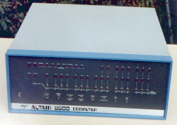
The MITS Altair 8800a and 8800b supported memory write protect, from the front panel. Bus pin 20 and 70 are output from the FRONT PANEL board, for memory protect (70) and memory unprotect (20). These signals were active high when the address bus had the address of a memory board which was to be write protected or unprotected. The address was set up on the front panel, manually; then the front panel switch "PROT/UNPROT" was manually toggled. These are NOT signals from the CPU card or the processor.
On the corresponding MEMORY BOARD of the same memory address, PROT or UNPROT would set or reset a flip flop to disable or enable (respectively) future writes to memory on that board. How much memory was write-protected was up to the board's design. For a few board schematics I looked at today, there was one, or two, flip-flops. Addressing any memory location on that board when PROT or UNPROT was active would set or clear the flip-flop selected by that address. Typically the block was 4K bytes; typical boards had anywhere from 1K bytes of memory to 16K bytes. (A flip-flop is a circuit holding one memory bit, as a persistant control signal.)
Memory boards with write protect also provided a bus signal, /PS (pin 69), which was active low when the board (or block on the board) was addressed and write-protected. The 8800b FRONT PANEL would display this as the PROT STATUS LED. Again, this is a front panel signal and not a signal to the CPU board or processor.
Write-protected memory was a feature on minicomputers, including the DG Nova 1200 which alledgedly influenced the Altair 8800a design. This scheme for microcomputers fell out of favor, as front panels became out of favor and as write-protected memory became disused. Some later memory cards provided write-protect switches on the board. The user would reach inside the S-100 card cage and toggle the on-board DIP switch for that memory bank, in use of course. (Many people ran their systems without covers for convenience and cooling.)
On subsequent S-100 cards and on IEEE-696 cards, many manufacturers wired pins 20 and 70 to ground; and pin 69 was unused. However, the IMSAI CP-A front panel schematic shows pin 20 as a line labled "T5". The text circuit description does not mention this signal. The schematic shows this signal as a line, pulled up with a resistor to +5 volts, which goes to several flip-flops used with front-panel controls. The CP-A does not support MEM PROT or MEM UNPROT or /PS.
I did not understand this CP-A feature until Thomas "Todd" Fischer, of IMSAI and imsai.net explained it in a post on comp.os.cpm of July 2006 titled "Cromemco 64FDC and Front Panel Operation":
"IMSAI originally (pre-IEEE-696 S-100 Bus Specs c. late 1977) intended for pin 20 to disable the one-shots (when pulled LOW) for the EXAMINE and DEPOSIT functions provided on the Front Panel as a feature (optional modification of the RUN/STOP switch to provide hardware WRITE PROTECT/UNPROTECT for the early static memory boards such as the RAM 3 and RAM IIIA. Original early IMSAI kits included a small piece of film mask that could be placed over the RUN/STOP region of the photo mask to display PROTECT/UNPROTECT (of memory) after requiring the RUN/STOP switch. Cromemco, Godbout, Parasitic Engineering, and other Left Coast manufacturers who were instrumental in establishing the IEEE spec felt that the "Roberts Bus/Altair" needed more ground lines, so tried to establish redundant grounds in locations that were deemed obsolete. Thus, Joe Killian's simple solution to killing MEM WRITES via hardware met its ignoble end!
I saw a small number of systems come through IMSAI Customer Service in the early years that actually had this modification, but I believe such efforts were motivated more by the "Bells and Whistles" allure than by practical need for such a feature. The original IMSAI 8080 User Reference manual includes a full-size copy of the optional mask, but the poor quality of reproduction renders it more "for the curious" than the practical." - Todd Fischer
From experience I know that when a card with grounded pin 20 is placed in an IMSAI with a front panel, the system stops working; it works again when the card is removed. The solution is dirt-simple, assisted by the fact that pin 70 (grounded on the CP-A) is immediately on the other side of the connector from pin 20. I simply put a very small piece of paper over BOTH pin 20 and 70 on the board, looping it over the edge of the edge connector; and I insert it carefully into its bus connector. Sometimes I'll put a bit of transparent tape over the paper JUST large enough to make contact on either side of the pin; but not so large as to cover the adjacent pins. The paper is not pulled off during insertion and it's held by the connector in place.
It's funny to explain all this decades later, when notions of "front panel" and "write protect" and even "reach inside the computer" are alien ideas. And, when flip-flops are (or were) a kind of shoe and not a design component.
References: schematics from manuals for IMSAI, Altair/MITS, Morrow products. Read the manuals! Also I have some bus signal lists on this page of S-100 bus signals. My page on MITS/Altair docs is right here. All my S-100 Web pages are referenced from my S-100 home page.
Copyright © 2006 Herb Johnson except portions as quoted which are copyright by originator.