![[pdp8/e panel]](8e_panel_1.jpg)
This Web page last updated Jan 27 2022. In Dec 2021 I'm working on a PDP-8/e front panel
register select switch. See my working PDP-8/f on this linked Web page. See my other DEC minicomputers as listed on my DEC Web page.
To email me, see see my ordering Web page for my email addresses.
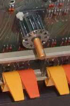
Here's a view of a complete registers switch on a PDP-8/? front panel. Compare it to my 8/e panel's broken switch. My switch lacks the central brass shaft, apparently it broke off the plastic cylinder inside the switch.
To restore the switch I'd have to cement a plastic disk inside the top of that rotating cylinder. And, the disk would have to anchor a brass shaft through its center. I judge that a difficult repair, certainly hard to do in place. In any event, I couldn't readily assess or repair the mechanism on-board. So I decided to remove it. Later I decided to hack up a rotary switch replacement from something available decades after this 1970's product.
![[pdp8/e panel]](8e_panel_mech_sw.jpg) This switch is photographed from a PDP-8/e or /f front panel. It shows use of
a 12-position mechanical switch (count the dimples around the switch). It's likely the
PC board layout was modified accordingly.
This switch is photographed from a PDP-8/e or /f front panel. It shows use of
a 12-position mechanical switch (count the dimples around the switch). It's likely the
PC board layout was modified accordingly.
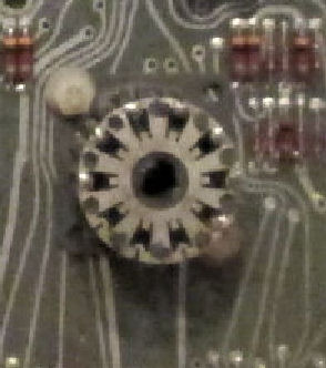
![[pdp8/e panel]](8e_panel_reed_sw.jpg) This switch is photographed from a PDP-8/e or /f front panel. Date stamp on
the PC board is August 1971. PC board 50090561, 5409052 (numbers not reliable).
It shows use of
an 8-position magnetic-reed switch (count the reeds around the switch). Unlike
my panel, the center shaft is intact. The black tubes between the reeds, are
black plastic structures. A magnet is rotated by the shaft to operate the switches,
which have a common connection on the switch-top metal disk as shown.
This switch is photographed from a PDP-8/e or /f front panel. Date stamp on
the PC board is August 1971. PC board 50090561, 5409052 (numbers not reliable).
It shows use of
an 8-position magnetic-reed switch (count the reeds around the switch). Unlike
my panel, the center shaft is intact. The black tubes between the reeds, are
black plastic structures. A magnet is rotated by the shaft to operate the switches,
which have a common connection on the switch-top metal disk as shown.
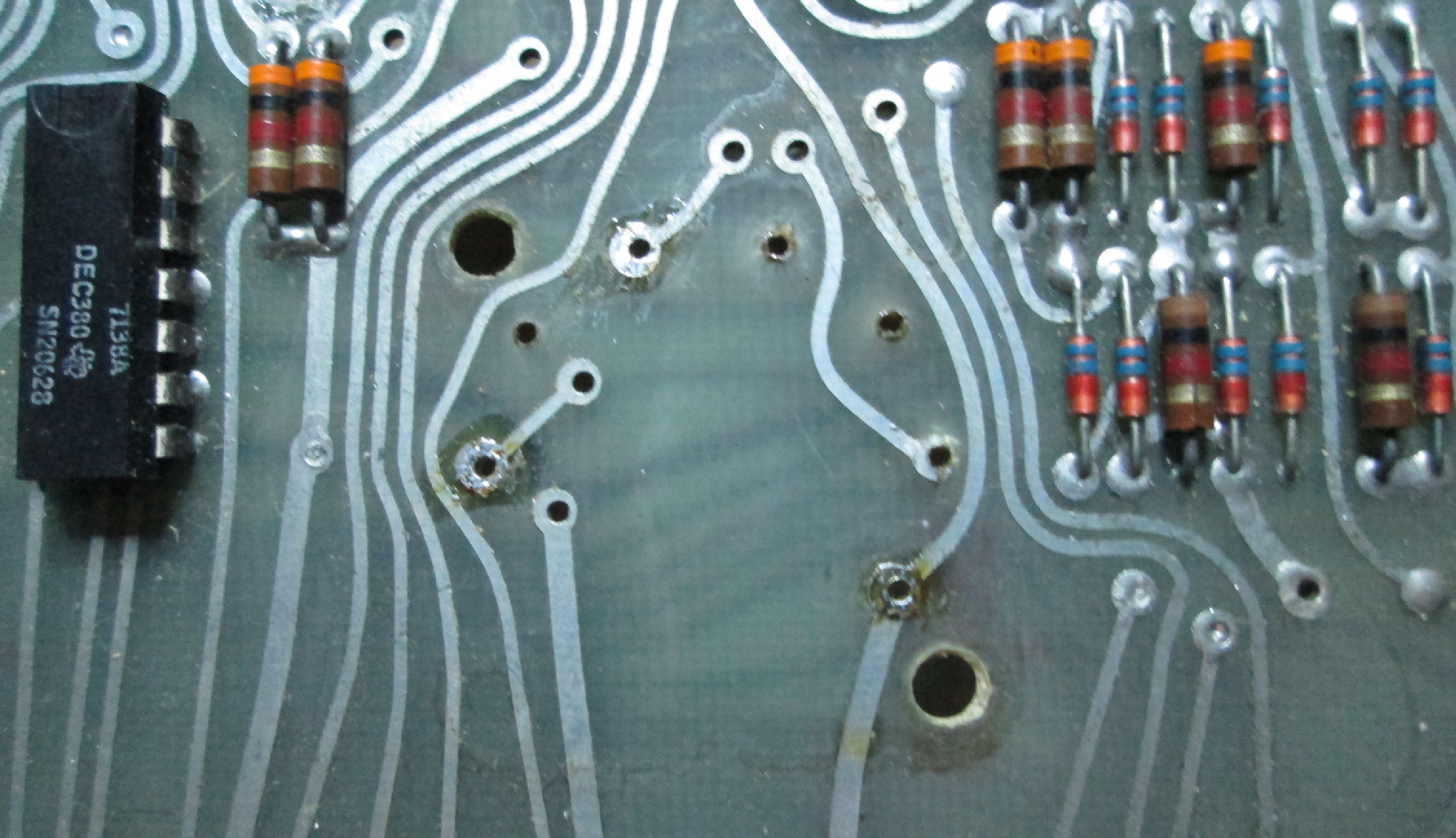
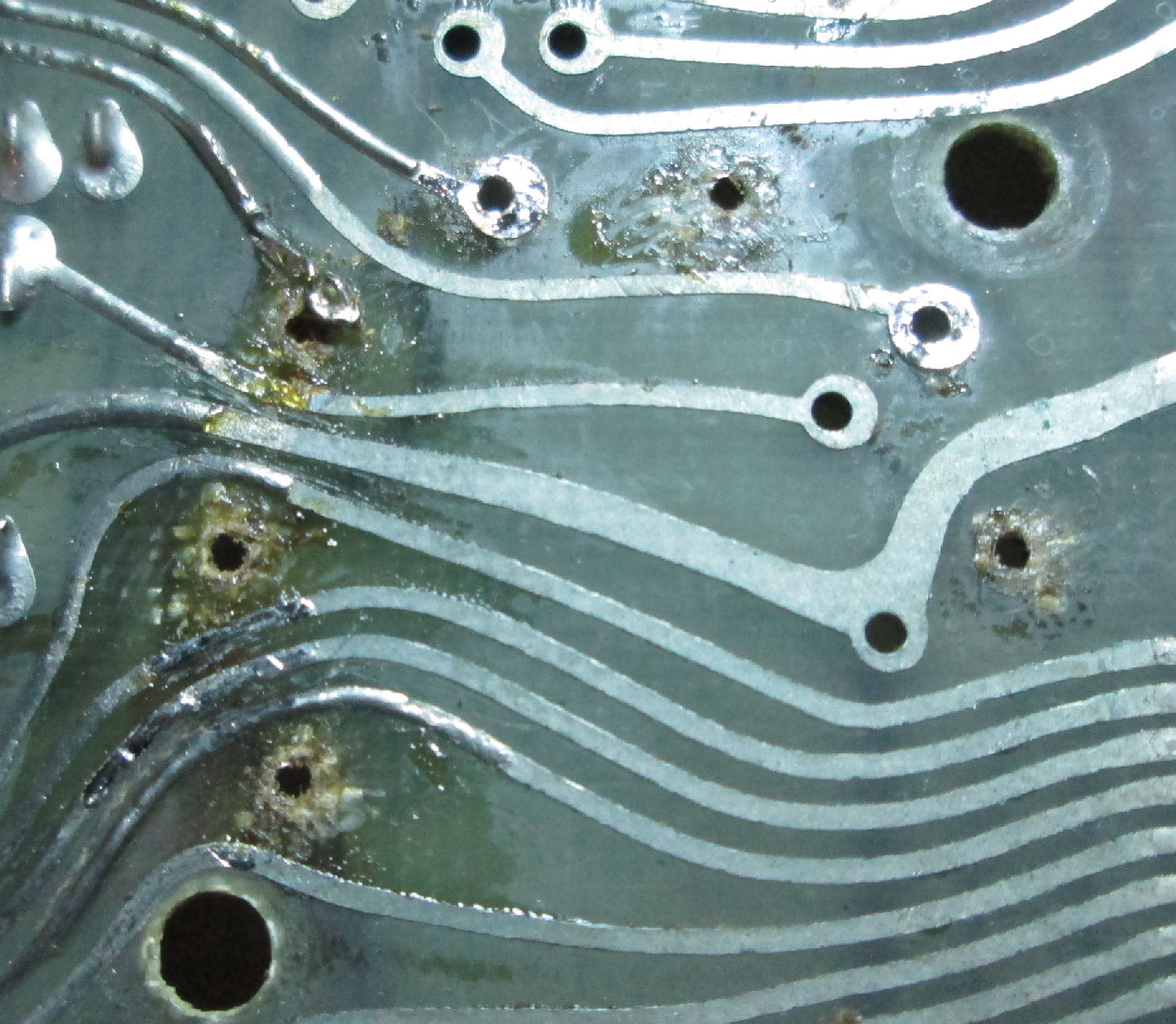
![[pdp8/e panel]](8epanel_remv3.jpg)
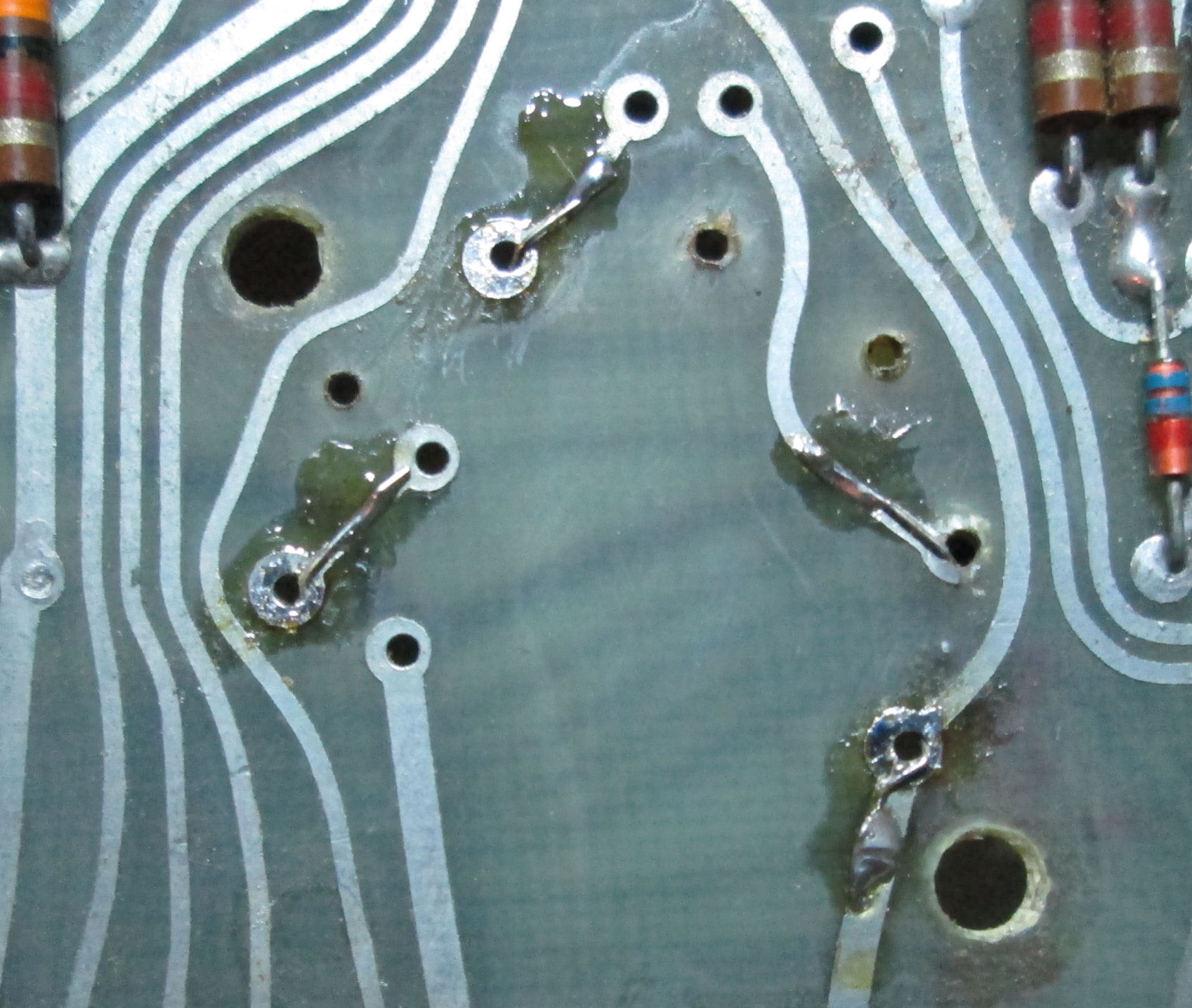
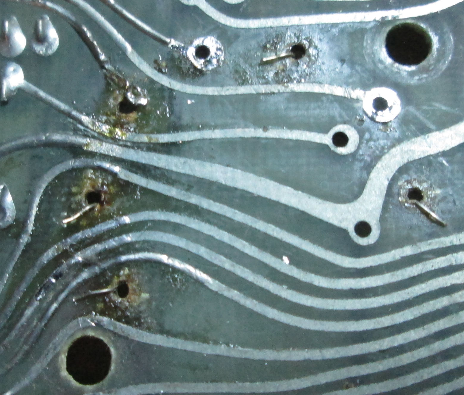
I desoldered the switch mechanism from the front panel PC board. The following are photos of the PC board at the switch. Here's a view from the front, component side. Here's a view from the back. To show their relationship, Here's a transparent view through from the back. NOte the damage to the PC board on either side. I was not the first to pull this switch off.
In removing the switch, I found damage to the PC board feed throughs and lands of the switch. YOu can see that in the removal photos above. Long ago, I repaired PC boards with little copper feed-through cylinders
and PC board "lands" or those copper loops. I didn't even try to find them in 2021. So I improvised. I looped #30 wire-wrap wires through the feed-holes and soldered them to the
available trace. As each hole only had one trace, I had limited choices. Here's the loops from the non-component side.
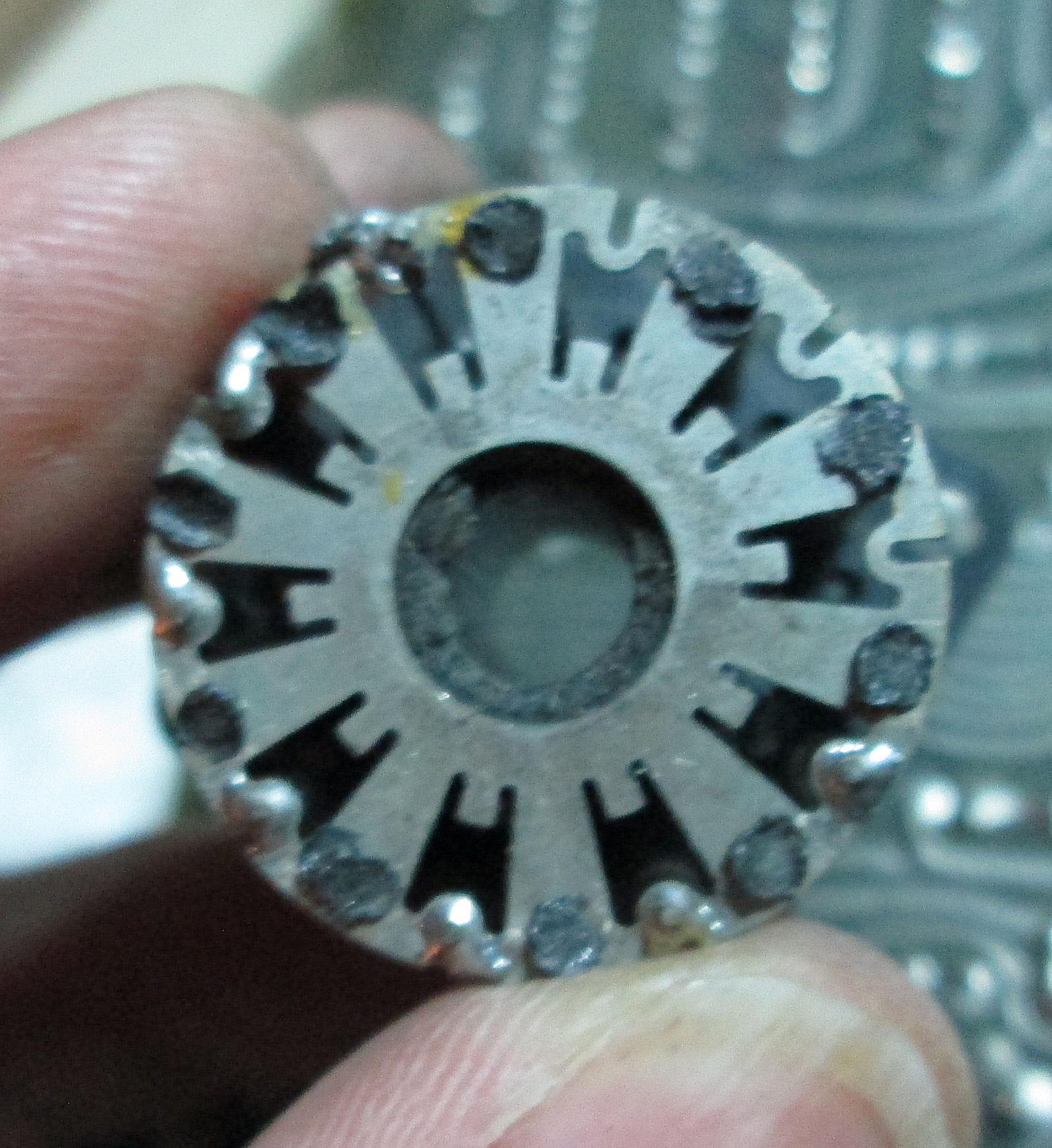
![[pdp8/e panel]](8epanel_reed2.jpg)
Of course I was able to remove the reed switch assembly intact. Here's a view of the top of the switch. At the center you can see a ring of black plastic. That's where the break occurred, that top disk held the brass shaft of the switch. The top of the mech is metal, with six solder points to the top end of six reed switches. The seventh, is a bare wire which of course is the "common" for the six-position switch. As mechanically designed, there's 10 positions around the switch - one would use up to nine reeds presumably.
here's a side view of the reed mech. It reveals the glass reed switches. Inside the outer cylinder of reeds and plastic posts, there's an inner cylinder that rotates and holds a magnet. The magnet likely closes the reeds when its in close proximity.
Here's a view of the bottom of the mech, where it contacts the PC board. Note there's 10 positions, of which six are in use plus a 7th for the common wire. The common wire attaches to the top metal disk of the assembly.
![[pdp8/e panel]](8e_panel_cmp.jpg)
In looking for any possible replacement as a conventional multiposition switch, note I'd need a 10-position rotary switch, to match the 10 positions of the assembly. However, I found in searching for rotary switches, the most conventional ones are 12-position (of which some are populated with contacts or not). I found a convenient 7-position switch on Amazon for $10 delivered in days (not 4 for $10 long delivery from Asia). As I've noted, there's actually 12 positions: only 7 are in use and the 8th is common. But it looked like the positions were in about the same locations as on the magnetic switch.
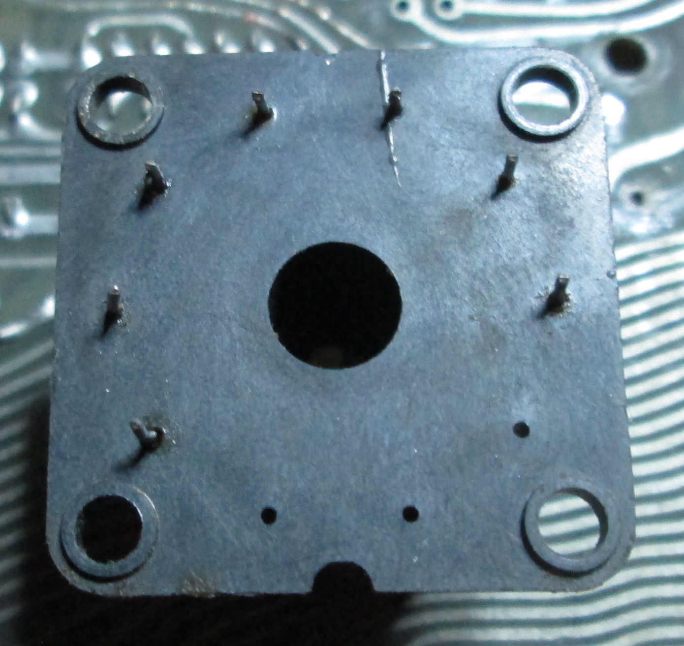
In days the Amazon mech switch arrived. Here's a view of the bottom of both switches. Of course the magnetic switch is on the left, the 8-throw on the right. 1) The mounting holes on the reed switch are very close to the screw-distance on the mech switch. Diameter of both switches are very similar. Also both switches are close in height.
2) The common terminal on both is at the far counter-clockwise position AND just above the left-hand mounting screw/hole. 3) Locations for the wire-lugs on both switches are fairly closely aligned. So: wiring
is a simple matter of almost vertical wires from lugs to PC board.
So my strategy, will be to extend the two screws on the mech switch, through a short piece of insultating plastic, to extend into the PC board holes. In principle I could etch a PC board to get the alignment exactly right. I may simply drill holes and extend wires through instead.